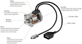
In each plant, the mechanical movement of different equipments is caused by an electric prime mover (motor). Electrical power is derived from either utilities or internal generators and is distributed through transformers to deliver usable voltage levels.
Electricity is found in two common forms:
• AC (alternating current)
• DC (direct current).

Electrical equipments can run on either of the AC/DC forms of electrical energies. The selection of energy source for equipment depends on its application requirements. Each energy source has its own merits and demerits.
Industrial AC voltage levels are roughly defined as LV (low voltage) and HV (high voltage) with frequency of 50–60 Hz. An electrical circuit has the following three basic components irrespective of its electrical energy form:
• Voltage (volts)
• Ampere (amps)
• Resistance (ohms).
1. Voltage is defined as the electrical potential difference that causes electrons to flow.
2. Current is defined as the flow of electrons and is measured in amperes.
3. Resistance is defined as the opposition to the flow of electrons and is measured in ohms.
All three are bound together with Ohm’s law, which gives the following relation between the three:
- V = I × R
(a) Power
In DC circuits, power (watts) is simply a product of voltage and current.
- P =V × I
For AC circuits, the formula holds true for purely resistive circuits; however, for the following types of AC circuits, power is not just a product of voltage and current.
Apparent power is the product of voltage and ampere, i.e., VA or kVA is known as apparent power. Apparent power is total power supplied to a circuit inclusive of the true and reactive power.
Real power or true power is the power that can be converted into work and is measured in watts
Reactive power If the circuit is of an inductive or capacitive type, then the reactive component consumes power and cannot be converted into work. This is known as reactive power and is denoted by the unit VAR.
(b) Relationship between powers
- Apparent power (VA) = V × A
- True power (Watts) = VA × cosφ
- Reactive power (VAR) = VA × sinφ
(c) Power factor
Power factor is defined as the ratio of real power to apparent power. The maximum value it can carry is either 1 or 100(%), which would be obtained in a purely resistive circuit.
- Power factor = True power / Apparent power
Types of circuits
There are only two types of electrical circuits – series and parallel.
A series circuit is defined as a circuit in which the elements in a series carry the same current, while voltage drop across each may be different.

A parallel circuit is defined as a circuit in which the elements in parallel have the same voltage, but the currents may be different.

Transformer
A transformer is a device that transforms voltage from one level to another. Transformer working is based on mutual emf induction between two coils, which are magnetically coupled. When an AC voltage is applied to one of the windings (called as the primary), it produces alternating magnetic flux in the core made of magnetic material (usually some form of steel). The flux is produced by a small magnetizing current which flows through the winding.
The alternating magnetic flux induces an electromotive force (EMF) in the secondary winding magnetically linked with the same core and appears as a voltage across the terminals of this winding. Cold rolled grain oriented (CRGO) steel is used as the core material to provide a low reluctance, low loss flux path. The steel is in the form of varnished laminations to reduce eddy current flow and losses on account of this.

There is a very simple and straight relationship between the potential across the primary coil and the potential induced in the secondary coil. The ratio of the primary potential to the secondary potential is the ratio of the number
of turns in each and is represented as follows:
- N1/N2 = V1/V2
Current-induced
When the transformer is loaded, then the current is inversely proportional to the voltages and is represented as follows:
- N1/N2 = V1/V2= I2/I1


Comments
Post a Comment