A force exerted on a body can cause a change in either the shape or the motion of the body. The unit of force in SI system is the newton (N) and CGS system is dyne. No solid body is perfectly rigid and when forces are applied to it, changes in dimensions occur. Such changes are not always perceptible to the human eye since they are negligible. For example, the span of a bridge will sag under the weight of a vehicle and a spanner will bend slightly when tightening a nut. It is important for civil engineers and designers to appreciate the effects of forces on materials, together with their mechanical properties of materials.

There are three main types of mechanical forces that can act on a body. They are:

There are three main types of mechanical forces that can act on a body. They are:
- Tensile force
- Compressive force and
- Shear force
1. Tensile force
Tensile force that tends to stretch a material, as shown in the figure 1 below.

Figure 1: Tensile force
For example,
- Rubber bands, when stretched, are in tension.
- The rope or cable of a crane carrying a load is in tension.
- When a nut is tightened, a bolt is under tension.
A tensile force will increases the length of the material on which it acts.
2.Compression Force
Compression Force is the application of power, pressure, or exertion against an object that causes it to become squeezed, squashed, or compacted. Objects routinely subjected to compression forces include columns, gaskets, disc brakes, and the components of fuel cells.
Since columns are used to support structures, they are always subjected to axial compression forces. By studying columns, one can get an understanding of the failures caused by compression forces. The effects of such forces depend upon the geometry of the column and the physical properties of the column material.
Under compression, short columns are dominated by their material strength limits. Figure 1 shows the failures that occur in ductile and brittle columns. However, as the length of the compression member increases, geometry and stiffness play important roles in the failure mechanisms.
Figure 2 shows the failure of an intermediate column under compression due to kneeling. Kneeling occurs when the inelastic limit of the member is reached. For a long (slender) column (Figure 3), buckling occurs before the stress exceeds the strength of the column material. For example, pushing on the ends of a business card reproduces the buckling of a long column.
 and Brittle (right), Short Compression Members") | ") |  |
Fig 1: Failures of Ductile (left) and Brittle (right), Short Compression Members
|
Fig 2: Failure of Intermediate Compression Member Showing Kneeling (Inelastic Buckling)
|
Fig 3: Buckling in a Long Compression Member
|
As stated above, columns are not the only structures subjected to compression forces. Consider, for example, brake discs. They are designed to withstand the compressive forces of braking. However, interaction of the various brake components often causes brake squeal.
Bakar, Ouyang, and Titeica reported on, “Modeling and Simulation of Disc Brake Contact Analysis and Squeal” at the 2005 Malaysian seminar on Advances in Noise, Vibration and Comfort. In their research, they used Fujifilm Prescale®, pressure indicating film, to characterize the compression forces on brake discs (Figures 4 and 5).
 |  |
Fig 4: Fujifilm Prescale® Film Placed on a Brake Pad
|
Fig 5: Fujifilm Prescale® Shows the Pressure Distribution Resulting from Compression Force on Brake Disc.
|
Fujifilm Prescale® is a Mylar-based film that contains a layer of tiny microcapsules. The application of force upon the film causes the microcapsules to rupture, producing an instantaneous and permanent high resolution topographical image of pressure variation across the contact area. Simply place Fujifilm Prescale® film between any two surfaces that touch, mate, or impact. Apply pressure, remove it, and immediately the film reveals the pressure distribution profile that occurred between the two surfaces
The data obtained by using Fujifilm Prescale® helped Bakar, Ouyang, and Titeica conclude that a stiffer caliper and disc can eliminate unstable frequencies that caused brake squeal during the compression force of braking.
A second example of Fujifilm Prescale® being used for research into compression force was published by Mikko Mikkola (http://www.tkk.fi/Units/AES/studies/specials/mikkola1.pdf). This work was titled, “Modifications to a PEM Fuel Cell Stack.” The Fujifilm Prescale® was used to measure contact pressures between the cathode flow field plate and the gas diffusion layer in a GlobeTech fuel cell.
The pressure distribution within the fuel cell is shown in Figure 6. The Fujifilm Prescale® data show that pressure varied between 101 and 341 psi. These data helped Mikkola identify several flaws in the fuel cell design.

Fig 6: Pressure Distribution in GlobeTech Fuel Cell
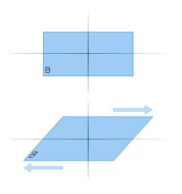
3.Shear force
Shearing forces are unaligned forces pushing one part of a body in one direction, and another part of the body in the opposite direction. When the forces are aligned into each other, they are called compression forces. An example is a deck of cards being pushed one way on the top, and the other at the bottom, causing the cards to slide. Another example is when wind blows at the side of a peaked roof of a home - the side walls experience a force at their top pushing in the direction of the wind, and their bottom in the opposite direction, from the ground or foundation. William A. Nash defines shear force in terms of planes: "If a plane is passed through a body, a force acting along this plane is called a shear force or shearing force.
Shear force of steel and bolts
Here follows a short example of how to work out the shear force of a piece of steel. The factor of 0.6 used to change from tensile to shear force could vary from 0.58 - 0.62 and will depend on application.
Steel called EN8 bright has a tensile strength of 800 MPa and Mild steel has a tensile strength of 400 MPa.
To work out the force to shear a 25 mm diameter round steel EN8 bright;
Area of the 25 mm round steel in mm2 = (12.52)(π) = 490.8 mm2
0.8 kN/mm2 × 490.8 mm2 = 392.64 kN = 40 ton × 0.6 (to change force from tensile to shear) = 24 ton
When working with a bolted joint, the strength comes from friction between the materials bolted together. Bolts are correctly torqued to maintain the friction. The shear force only becomes relevant when the bolts are not torqued.

A bolt with property class 12.9 has a tensile strength of 1200 MPa (1 MPa = 1 N/mm2) or 1.2 kN/mm2 and the yield strength is 0.90 times tensile strength, 1080 MPa in this case.
A bolt with property class 4.6 has a tensile strength of 400 MPa (1 MPa = 1 N/mm2) or 0.4 kN/mm2 and yield strength is 0.60 times tensile strength, 240 MPa in this case.
In case of fastners, proof load is specified as it gives a real life picture about the characteristics of the bolt.


Comments
Post a Comment